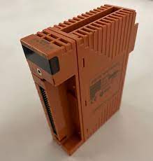
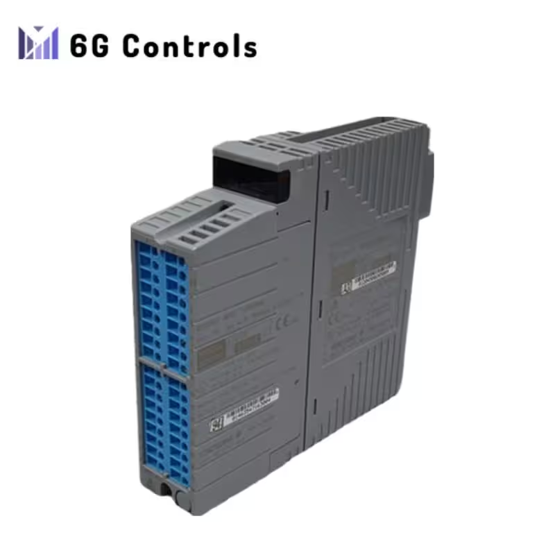
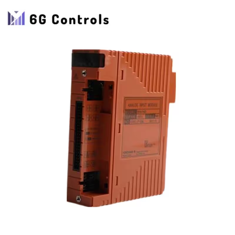
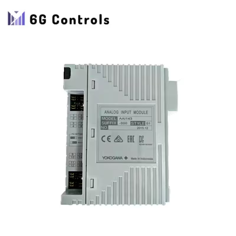
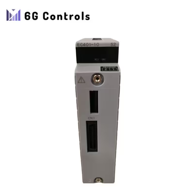
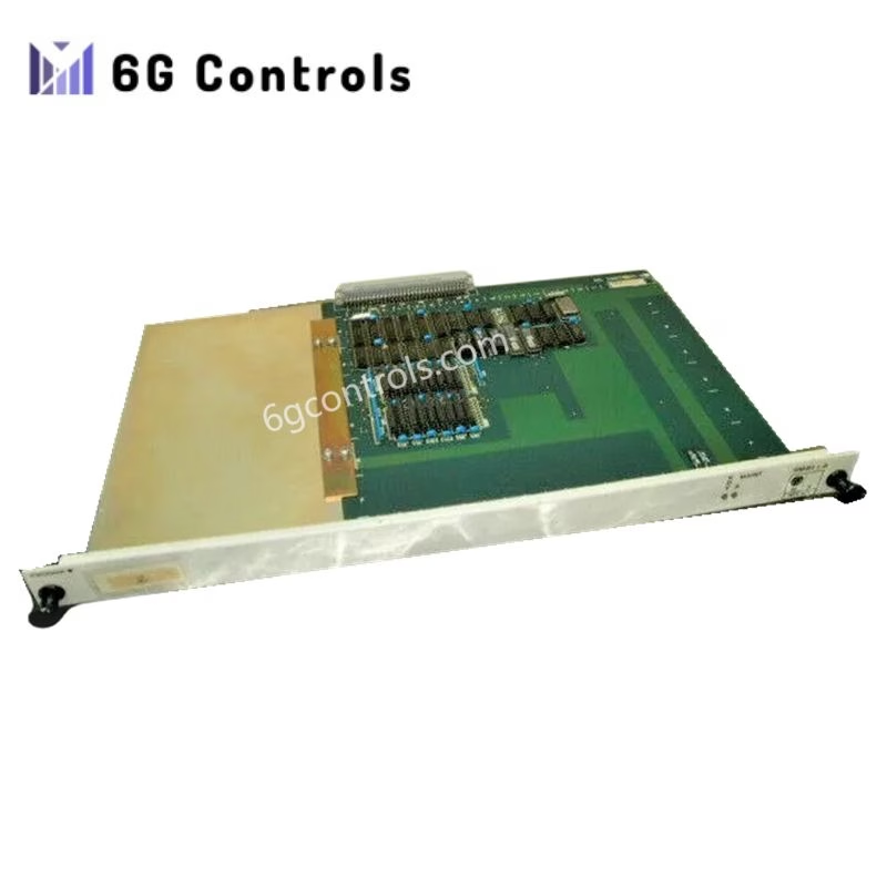
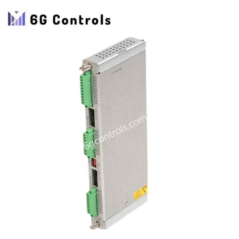
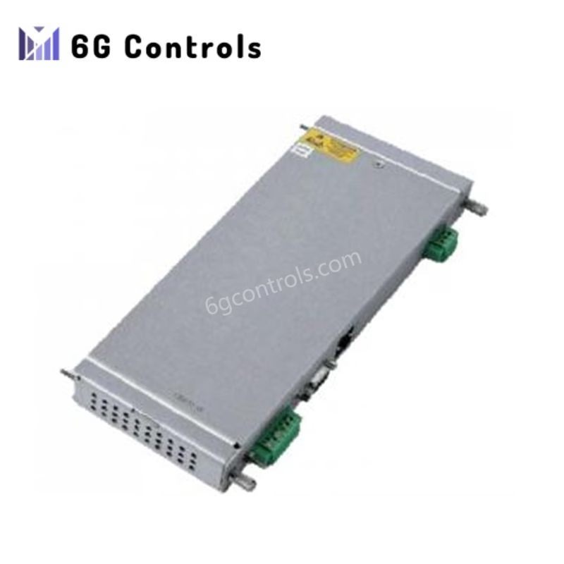
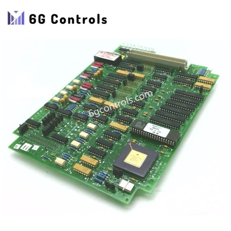
The Yokogawa SDV144-S13 Digital Input Module has been discontinued, and its new replacement is the SDV144-S53 Digital Input Module.If you still require the SDV144-S13, we have a substantial quantity of brand new stock available for immediate delivery.
Input Module:
- Input modules accept contact signals from the field. SDV144 can be made dual-redundant.
Specifications:
- Model: SDV144
- Number of Inputs: 16-channel, module isolation (*3)
- Input Signal: No-voltage contact
- ON: 1 kΩ maximum
- OFF: 100 kΩ minimum
- Input Current: 6 mA ± 20% (External power supply, 24 V DC at 0 Ω input)
- Contact Rating: 24 V DC +20% / -10% (*4), 10 mA or greater
- External Power Supply: 24 V DC +20% / -10% (*3) (*4)
- Current capacity: 200 mA
- Instantaneous Maximum Permissible Input Voltage: 30.0 V DC
- Input Response Time: 40 ms maximum
- **Withstand Voltage (1) (2): 2 kV AC between input signal and system for 1 minute, 16-input line collectively connected (*5)
- Current Consumption: 290 mA maximum (5 V DC)
- 140 mA maximum (24 V DC)
- Weight: Approx. 0.36 kg (For pressure clamp terminal block or MIL cable)
- Approx. 0.41 kg (With signal cable interface adapter)
External Connection:
- Pressure clamp terminal
- MIL cable
- Dedicated signal cable (AKB331)
*1: These voltages show the case using the field power supply floating. When the field power supply is grounded, the system (functional) ground is connected to the field ground, which is not isolated. For higher noise immunity, floating the field power supply is recommended.
*2: When the withstanding voltage of the field power supply between the secondary side and the ground is lower than the value shown in the table above, these voltages are adopted as the withstanding voltage of the field power supply.
*3: The number of input channels that a user can use and external power supply are restricted in the case of SDV144-S≤C. Refer to “ProSafe-RS Outline of I/O Modules (for FIO)” (GS 32P06K60-01EN).
*4: The contact rating and the external power supply of SDV144 style code S1, S2, and S3 are 24 V DC ± 5%.
*5: When connecting SDV144 and SED4D terminal board using the dedicated signal cable, the withstand voltage is 500 V AC (between input signal lines and system). If MIL connector cables are used, the withstand voltage depends on their cable’s electrical specifications.
The Yokogawa SDV144 Digital Input Module comes with various model and suffix codes to accommodate different configurations and requirements. Here are the available model and suffix codes:
Model: SDV144 Digital Input Module (16-channel, 24 V DC, module isolation)
Suffix Codes:
- -S: Standard type
- -5: For pressure clamp terminal block or MIL cable with no explosion protection
- -6: With signal cable interface adapter and no explosion protection (*1)
- -E: For pressure clamp terminal block or MIL cable with explosion protection
- -F: With signal cable interface adapter and explosion protection (*1)
- -3: With ISA Standard G3 and temperature (-20 to 70 °C)
- -C: With ISA Standard G3 and high-density installation (-20 to 70 ºC)
Option Codes:
- /B4S00: With pressure clamp terminal block for digital input (without surge absorber) [Model: STB4S-00]
- /B4S10: With pressure clamp terminal block for digital input (with surge absorber) [Model: STB4S-10]
- /B4D00: With dual-redundant pressure clamp terminal block for digital input (without surge absorber) (*2) [Model: STB4D-00]
- /B4D10: With dual-redundant pressure clamp terminal block for digital input (with surge absorber) (*2) [Model: STB4D-10]
- /PRP: With prevention pin of false insertion (*3)
- /CCC01: With connector cover for MIL cable (for flat ribbon cable) [Model: SCCC01]
- /CCC02: With connector cover for MIL cable (for discrete wire) [Model: SCCC02]
*1: When SDV144-S6 or -SF is selected, you cannot choose the option code for a pressure clamp terminal block and MIL cable connector.
*2: When this module is used in a dual-redundant configuration, order an additional module with the same specification but without option codes.
*3: When SDV144-S6 or -SF is selected, you can choose the option code for prevention pin of false insertion.
This flexibility in model and suffix codes allows users to customize the SDV144 Digital Input Module to meet specific requirements, including explosion protection, temperature range, and connector options.
Download Yokogawa SDV144-S13 Digital Input Module PDF Manual:SDV531-LE3
More Products:
| Brand | Model | Link |
|---|---|---|
| Yokogawa | SEC402-51 S1 | Link |
| YOKOGAWA | AAI543-S50 | Link |
| YOKOGAWA | CP451-10 | Link |
| YOKOGAWA | AAI143-H00 | Link |
| Yokogawa | ANB10D-425/CU2N | Link |
| Yokogawa | CP345 | Link |
| YOKOGAWA | EC401-11 | Link |
| YOKOGAWA | SB401-11 | Link |
| YOKOGAWA | AAI543-S03 | Link |
| YOKOGAWA | PW482-11 | Link |
| YOKOGAWA | AAI143-S03 | Link |
| YOKOGAWA | AAI143-S53 | Link |
| YOKOGAWA | AFV10D-S41211 | Link |
| YOKOGAWA | ANB10D-421/CU2N/NDEL | Link |
| Yokogawa | AAI841-H00 | Link |
| Yokogawa | SAI143-H63 | Link |
| Yokogawa | AAR145-S50 | Link |
| Yokogawa | ADM11C | Link |
| YOKOGAWA | ASD143-P00 | Link |
| YOKOGAWA | ANB10D-425/CU2N | Link |
| YOKOGAWA | AAI143-H50/A4S00 | Link |
| YOKOGAWA | AAI543-H50/A4S00 | LINK |
| YOKOGAWA | ALP111-S00 | LINK |
| YOKOGAWA | AFF50D-H41201 | LINK |
| YOKOGAWA | AIP504-10 | |
| YOKOGAWA | SDV144-S13 | |
| YOKOGAWA | SDV541-S13 | |
| YOKOGAWA | SAI143-H03 | |
| YOKOGAWA | SDV531-LFC | |
| YOKOGAWA | AAI143-S50 | |
| YOKOGAWA | SCP451-11 | |
| YOKOGAWA | PW301 | |
| YOKOGAWA | CP451-50 | |
| YOKOGAWA | ANB10D-420 | |
| YOKOGAWA | SAI143-H33 |
 6G Controls - Leading Supplier of New & Original PLC 、DCS Parts and Automation Controller
