GENERAL
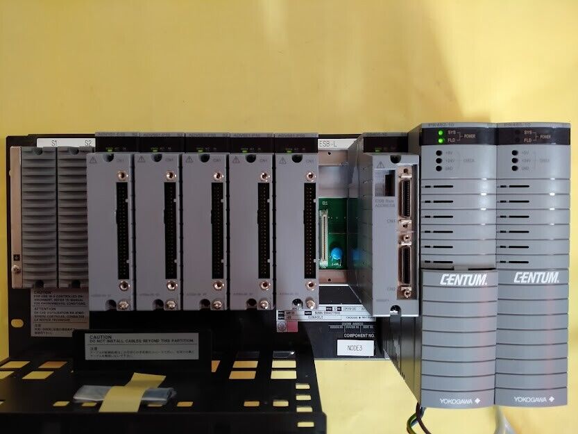
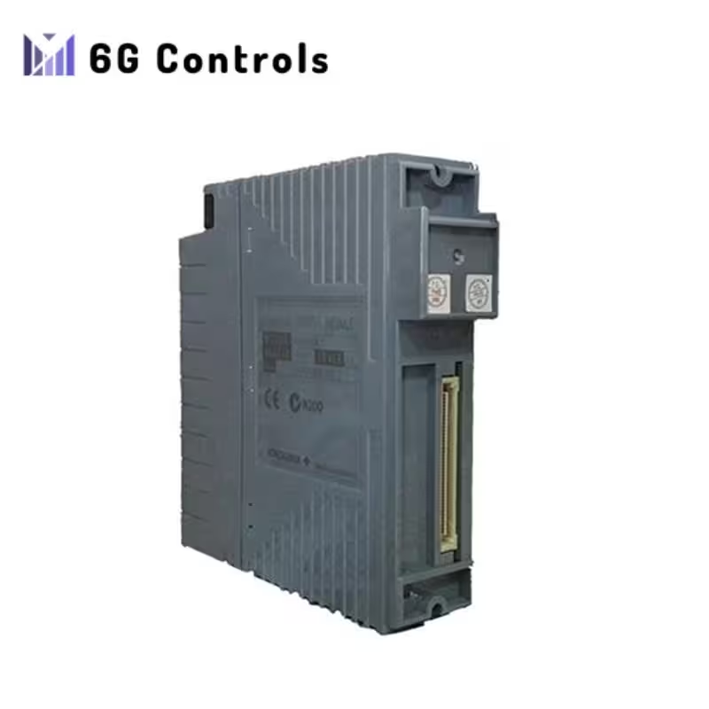
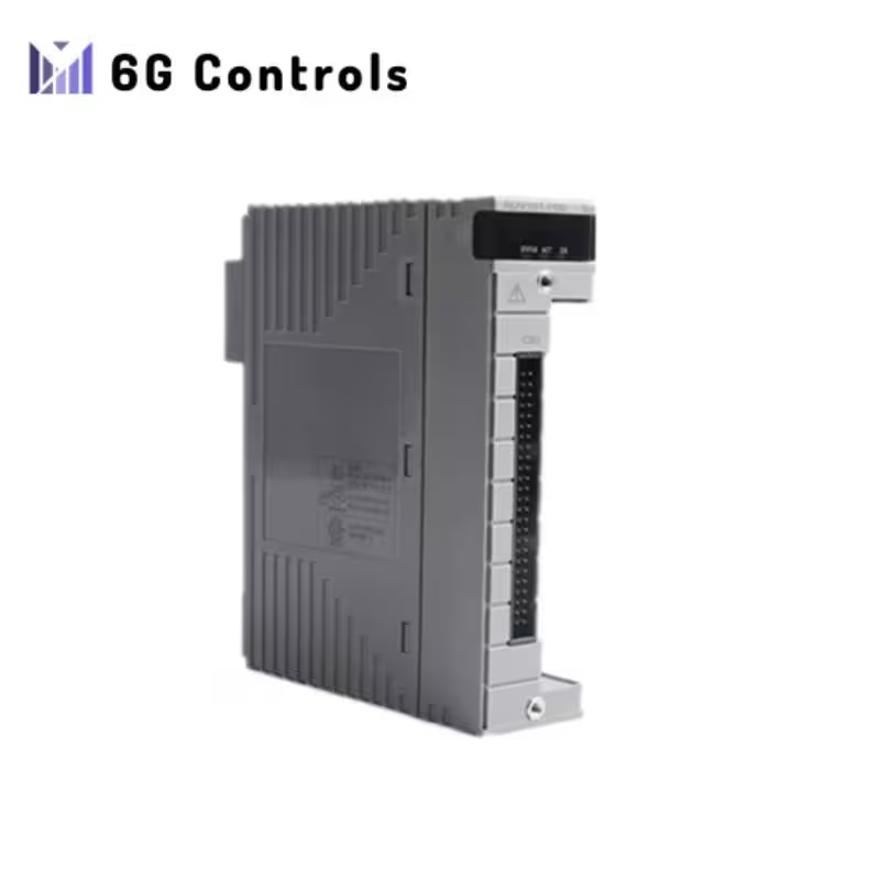
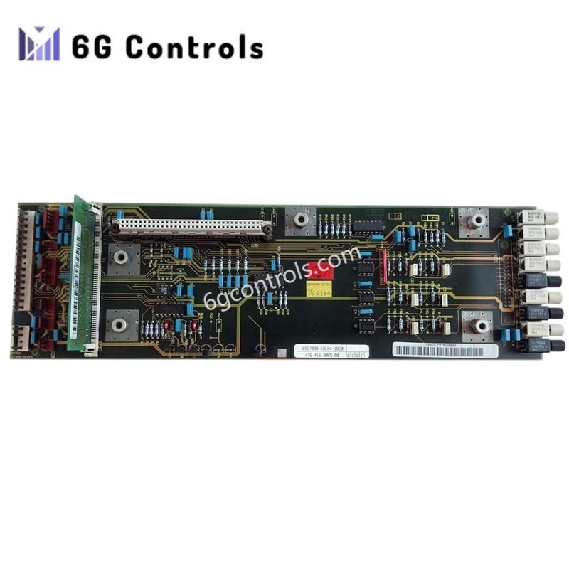
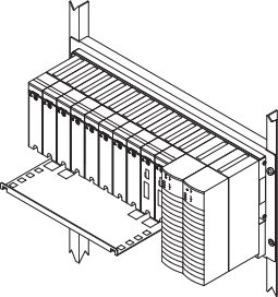
The Yokogawa ANB10D-425/CU2N ESB Bus Node Unit features an interface function that facilitates communication between analog I/O signals and contact I/O signals of a field with a Field Control Unit (FCU) via an ESB bus. It also supplies power to the I/O Modules. These node units are connected to the FCU via an ESB bus.
STANDARD SPECIFICATIONS
For installation specifications and environmental conditions common to the systems, refer to the documents: “N-IO System Overview (GS 33J62A10-01EN)” and “FIO System Overview (GS 33J60A10-01EN).”
No. of Node Units Connectable
| Field Control Unit | Software License | Total ESB Bus Node Units (ANB10) and Optical ESB Bus Node Units (ANB11) Connected per FCU |
|---|---|---|
| A2FV50o | VP6F1800 | Max. 8 |
| A2FV70o | VP6F1900 | Max. 8 |
| AFV30o, AFV40o*1 | VP6F1700 | Max. 13 (up to 11 in AFV40o) |
ESB Bus Node Connection
When connecting an ESB Bus Node Unit to FCU, install an ESB Bus Coupler Module (EC401 or EC402) to FCU (*1). EC401 or EC402 must be installed in slot 7 and slot 8. To configure a single setup, EC401 or EC402 must be in slot 7, and Slot 8 should be empty.
*1: A2FV50o, A2FV70o, AFV30o, or AFV40o.
Power Supply
Specify with Suffix Codes:
- Voltage: 100-120 VAC, Frequency: 50/60 Hz
- Voltage: 220-240 VAC, Frequency: 50/60 Hz
- Voltage: 24 V DC
Electric Power Consumption
- 100-120 VAC: 200 VA, 120 W
- 220-240 VAC: 230 VA, 120 W
- 24 V DC: 5.5 A
Weight
Approx. 10 kg (including 8 I/O Modules)
Mounting
- 19-inch Rack Mounting
- Rack mount (M5 x 4 screws)
- Insulation bash (accessory)
CONFIGURATION
Module Configuration
- Power Supply Module (PW481 or PW482 or PW484): Two modules in case of a dual-redundant configuration. Power supply to the I/O Modules and transmitters.
- ESB Bus Interface Slave Module (SB401): Two modules in case of a dual-redundant configuration.
- I/O Modules (*1): Max. 8
*1: Non-standard components. For ANB10 used with A2FV50 or A2FV70, only specific communication modules can be mounted.
LIMITATIONS OF INSTALLATION AND NOTICES FOR INSTALLATION
Certain limitations apply to the installation of I/O modules in the node unit, including quantity and allocation. Installation within specified ambient operating temperature conditions is also limited when mounting a node unit in the dedicated cabinet. When modules with built-in barriers are installed, an insulating partition (Part No. T9083NA) must be used.
EXTERNAL DIMENSIONS

MODELS AND SUFFIX CODES
Refer to the provided table for available models, suffix codes, and descriptions.
ACCESSORIES AND SPARE PARTS
Refer to the parts list for insulating bush details.
APPLICABLE STANDARDS
For applicable standards, refer to the “Integrated Production Control System CENTUM VP System Overview (GS 33J01A10-01EN).”
ORDERING INFORMATION
Specify the model and suffix codes. For explosion protection product selection, refer to TI 33Q01J30-01E.
TRADEMARKS
- “CENTUM” is a registered trademark or trademark of Yokogawa Electric Corporation.
- All other company or product names mentioned are trademarks or registered trademarks of their respective holders.
Read the PDF for more information: GS33J60F20-01EN
 6G Controls - Leading Supplier of New & Original PLC 、DCS Parts and Automation Controller
