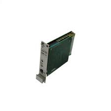
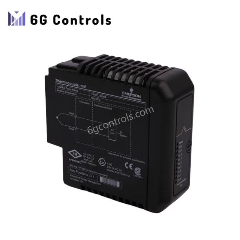
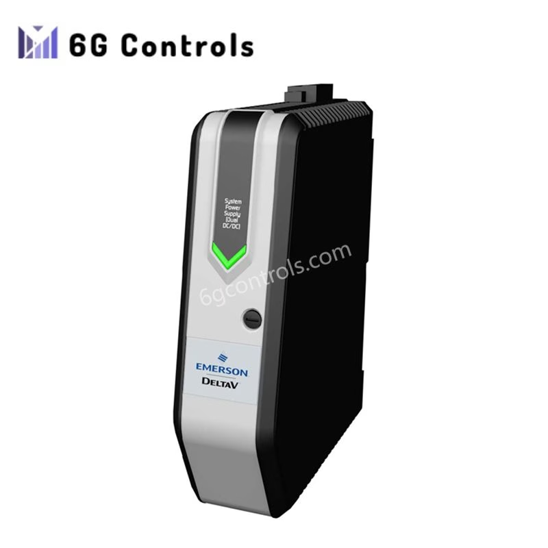
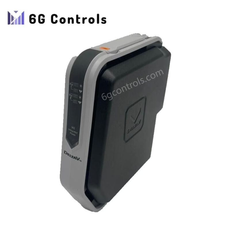
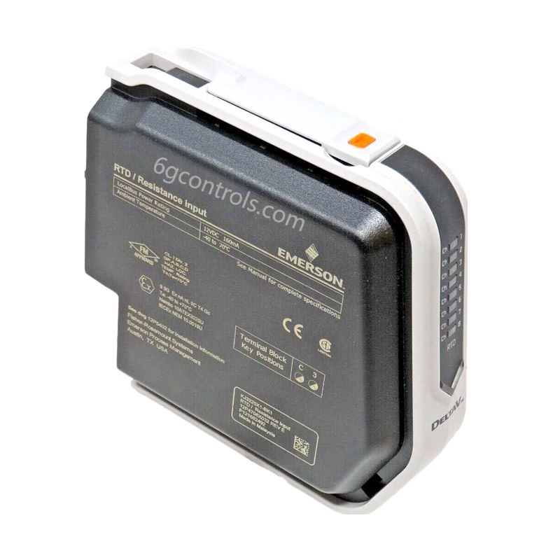
The Valve and Case Expansion Monitor is meticulously crafted for high reliability, specifically targeting a plant’s most critical rotating machinery. This 1-slot monitor seamlessly integrates with other AMS 6500 monitors, forming a comprehensive API 670 machinery protection monitor.
Applications for this monitor span across various industries, including steam, gas, compressors, and hydro turbomachinery.
Primary Functions:
The Valve and Case Expansion Monitor primarily serves to:
- Accurately Monitor Valve Position: It continuously tracks the position of the main steam inlet valve stem, typically displayed as a percentage open. This measurement offers valuable insights into the turbine’s current load, aiding operators in making informed decisions.
- Reliably Protect Machinery: By comparing monitored parameters against preset alarm setpoints, this monitor triggers alarms and relays when necessary, ensuring the machinery’s safety and integrity.
Case Expansion Monitoring:
Case expansion monitoring involves the use of two inductive displacement sensors (LVDTs), typically mounted axially and parallel to the shaft on each side of the turbine case. Unlike non-contact sensors like eddy current sensors, inductive sensors make physical contact.
This monitoring is especially critical during startup, as it allows both sides of the turbine case to be monitored for proper expansion rates. Failure to do so can result in the turbine “crabbing,” where the case bends, potentially leading to rotor-case collisions.
Channel Configuration:
- Channel 1: Capable of measuring static values such as case expansion and dynamic quantities like displacement, angles, forces, torsions, or other physical measurements obtained from inductive transducers.
- Channel 2: Reserved for static measurements and relative displacements relative to channel 1.
The AMS 6500 Machinery Health Monitor seamlessly integrates into PlantWeb®, providing operations with integrated machinery health information in conjunction with the Ovation® and DeltaV™ process control systems. The AMS software equips maintenance personnel with advanced predictive and performance diagnostic tools, allowing them to confidently and accurately identify early signs of machine malfunctions.

Key Features:
- Two-channel,3U size, 1-slot plug-in module decreases cabinet space requirements in half from traditional four-channel 6U size cards
- API670 compliant, hot swappable module
- Passwordprotected user configuration
- Self-checking facilities include monitoring hardware, powerinput, hardware temperature, sensor and cable
- Front and rear buffered andproportional outputs, 0/4-20 mA output, 0 – 10 V output
- Use with inductive displacement sensor 9350
Specification:
| Transducer Inputs | |
| Number of Inputs | Two, independent, differential inputs |
| Type of Inputs | Inductive, half bridge or full bridge
and differential transformers |
| Emerson Sensor Inputs | Part number: PR 9350/xx and K20315/xx |
| Isolation | Galvanically separated
from power supply |
| Input Impedance | 200 kΩ |
| Input Voltage Range | 3.6 VDC
(protected against over voltage) |
| Measuring Frequency Range | 0 – 100 Hz (-3 dB) |
| Measuring Range | |
| Range | Continuously adjustable with configuration software. One or both outputs may be inverted |
| Carrier Frequency | 4.75 kHz |
| Sensor Power Supply | Separate buffered sensor supply Galvanically separated from all system voltages and system supply voltage. Open and short circuit proof. |
| Nominal Supply Voltage | 4 V rms |
| Permissible Load | 120-600 Ω |
| Front Panel Outputs | |
| Green LED’s | Two LED’s, indicates channel OK separately for each channel. |
| Red LED’s | Four LED’s, indicates alert and
danger separately for each channel. |
| Front Panel Buffered Outputs | Two, identical to transducer
sensor inputs ±12 V, >100 kΩ load. |
| Mini DIN Configuration Socket | „ Module interface connection for configuration and parameter and status monitoring
„ RS-232. |
| Handle | Easily remove card and provide plate for module and sensor identification |
| Analysis | |
| Measurement Modes | Hot configurable for
dual-channel measurement, expansion measurement. |
| Configurable Parameters | „ Measuring range
„ Engineering units „ Sensitivity „ Alert and Danger |
| Rear Outputs Available | |
| Current Mode Outputs | 0/4-20 mA output for each channel proportional to main value Open/short circuit proof. |
| Permissible Load | <500 Ω |
| Accuracy | ±1% of full scale |
| Settling Time | Configurable, 0 – 10 seconds |
| Rear Buffered Outputs | Raw buffered output signal, 0 – 12 V peak to peak Open/short circuit proof |
| Frequency Range | 0 – 100 Hz (-3 dB) |
| Permissible Load | >100 kΩ |
| DC Voltage Outputs | 0 – 10 VDC output proportional to
main value Open/short circuit proof |
| Accuracy | ±1% of range |
| Permissible Load | >10 kΩ |
| Alarm Setpoints Alarm Time Delays | |
| Alert | „ Selectable normally open, normally closed 0 – 5 second delay per channel 0 – 36 second delay with A6740 relay card
„ Selectable to be blocked on channel not OK „ Adjustable range 5 – 100% of full scale value „ Resolution 1% of full scale value „ Alarm hysteresis on decreasing signal value, 0 – 20% of full scale value |
| Danger | „ Selectable normally open, normally closed 0 – 5 second delay per channel 0 – 36 second delay with A6740 relay card
„ Selectable to be blocked on channel not OK „ Adjustable range 5 – 100% of full scale value „ Resolution 1% of full scale value „ Alarm hysteresis on decreasing signal value, 0 – 20% of full scale value |
Protection Cards for AMS 6500 Classic Systems
- A6740-10 16-Channel Output Relay Module
- A6740-12 16-Channel Output Relay Module
- A6125 Case Piezoelectric Vibration Monitor
- A6120 Case Seismic Vibration Monitor
- A6824-R ModBus And Rack Interface, 4TE
- A6824 ModBus And Rack Interface, 6TE
- A6620 Process Input Monitor
- A6140 Shaft Absolute Vibration Monitor
- A6220 Shaft Eccentricity Monitor
- A6110 Shaft Relative Vibration Monitor
- A6312 Speed and Key Monitor
- A6312-8 Speed and Key Monitor
- A6630 Temperature Monitor
- A6210 Thrust Position, Differential Expansion, and Rod Position Monitor
- A6410 Valve and Case Expansion Monitor
 6G Controls - Leading Supplier of New & Original PLC 、DCS Parts and Automation Controller
