Velomitor Piezo-Velocity Sensor Specifications:*
- Standard 330500 Velomitor* Piezo-Velocity Sensor:
- Maximum Operating Temperature: +121°C (+250°F) due to signal conditioning electronics being located in the same case as the sensing element.
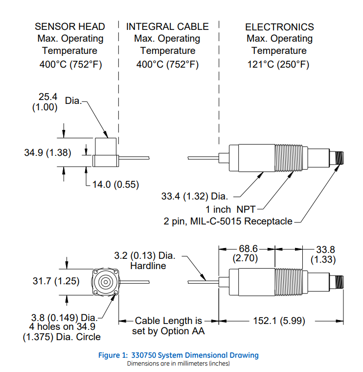
- High Temperature Velomitor System (HTVS) 330750 and 330752:
- Construction: Sensing element and signal conditioning electronics are segregated, connected via a hardline cable.
- Maximum Sensing Head Temperature: +400°C (+752°F).
- Advantages: Eliminates potential transducer failures from connector problems.
- Overall Transducer System Performance: Comparable to other Velomitor transducers but permits use at significantly higher temperatures.
Caution:
- Housing measurements for overall machine protection may not be effective in all cases, as common machine malfunctions often originate at the rotor.
- Proper physical installation of the transducer is essential to maintain its performance and ensure accurate machine vibration monitoring.
- Bently Nevada can provide engineering services and installation assistance upon request.
Electrical Parameters:
- Sensitivity: 5.7 mV/mm/s (145 mV/in/s) ±5%
- Frequency Response:
- 15 to 2000 Hz (900 to 120,000 cpm) ±3.0 dB
- 20 to 1000 Hz (1,200 to 60,000 cpm) ±0.9 dB
- Transient Temperature Sensitivity: 0.0762 mm/s/°C (0.003 in/s/°C), typical, as defined in ISO 5347-18:1993(E).
- Amplitude Range:
- Below 680 Hz: 635 mm/s (25 in/s) peak
- Above 680 Hz: 2940 m/s2 (300 g) peak (Vibration at frequencies above 2 kHz will decrease this range.)
- Transverse Sensitivity: Less than 5% of Sensitivity.
- Amplitude Linearity: ±2% to 152 mm/s (6 in/s) peak.
- Mounted Resonant Frequency: Greater than 5 kHz.
- Broadband Noise Floor (15Hz to 2kHz): 0.127 mm/s (0.005 in/s) rms nominal.
- Maximum Cable Length: 305 meters (1000 feet) with no degradation of signal.
Hazardous Area Approvals:
- North America:
- CSA/US/C certified for hazardous areas.
- Class I, Div I, Groups A, B, C, and D.
- Class II, Div I, Groups E, F, and G.
- Class III, Div I.
- Ex ia IIC, AEx ia IIC, T4 @ Ta = 100°C when installed with an approved zener barrier per BN drawing 168077.
- Ex nL IIC; Class I, Zone 2, Class I, Div 2, Groups A, B, C, D when installed per BN drawing 168077.
- Europe/ATEX:
- II 1 G Ex ia IIC T4, T4 @ Ta = -40°C – 100°C.
- II 3 G Ex nA IIC T4, T4 @ Ta = -40°C – 100°C.
Note: Current versions of the High-Temperature Velomitor System have the letter “G” preceding the serial number.
Dimensional Drawing – 330750 and 330752

Click Here for more infomation: https://www.6gcontrols.com/wp-content/uploads/2023/datasheet-pdf-manual-download/330750-80-05.pdf
 6G Controls - Leading Supplier of New & Original PLC 、DCS Parts and Automation Controller
